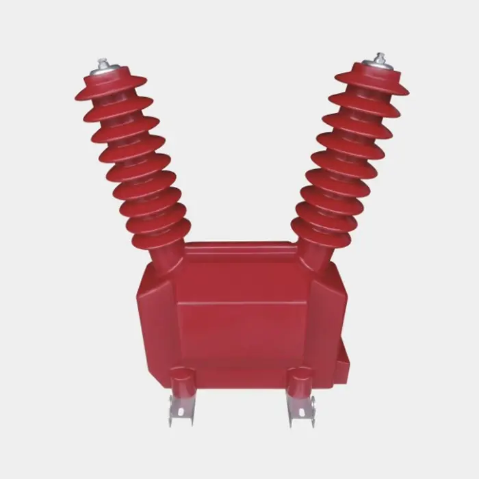
When the engineers of a 36 kV gas-insulated switchgear project needed a metering-class voltage divider that could ride out 70 kV lightning impulses and still keep ±0.2 % accuracy after twenty years of service, they did not pick a conventional wire-wound block. Instead, they selected a current-transformer-grade thick-film high-voltage resistor and reduced the divider length by more than one third while passing IEC 61869-1 on the first attempt. The story below explains why and how.
 Thick-Film High-Voltage Resistors
1. Challenge
The goal was to integrate three-phase voltage sensors inside a compact epoxy chamber shared with the disconnector. Space was tight, hotspot temperature could reach 115 °C, and the divider had to be non-inductive so that phase error stayed within ±3 minutes. Standard film or wire-wound resistors failed either on impulse flash-over or on long-term drift.
2. Specification
Rated continuous voltage: 36 kV r.m.s.
Lightning impulse: 70 kV peak (1.2/50 µs)
Accuracy class: 0.2 S (IEC 61869)
Temperature coefficient: ≤ 25 ppm/K
Self-inductance: ≤ 400 nH
Design life: 20 years, 8 000 h at 90 °C
3. Solution
A thick-film element fired on 96 % alumina was chosen. The planar meander trace is only 25 µm thick, so inductance stays below 300 nH and the negative TCR of the ink can be laser-trimmed against the positive TCR of the substrate, giving a net figure of ±25 ppm/K without external compensation.
Two 60 MΩ segments in series produced 120 MΩ, limiting divider power to 0.4 W and holding thermal drift under 0.05 %.
4. Impulse verification
Five samples underwent 50 shots of 70 kV 1.2/50 µs, 30 s interval. Mean flash-over value was 78 kV, an 11 % safety margin. Resistance shift was < 0.08 %, well inside the 0.2 % acceptance band.
5. Long-term stability
A 1 000 h endurance test at 90 °C and 1.2 × rated voltage showed ΔR/R = +0.12 %. Extrapolated 20-year drift is 0.28 %, comfortably below the 0.5 % budget required for 0.2 S class.
6. Mechanical gains
38 % shorter than the earlier wire-wound stack, freeing 28 mm of vertical space
35 % lighter, reducing seismic load on the epoxy housing
Single-body construction removes solder joints that often crack under vibration (IEC 62271-100, 2 g)
7. Field results
Since the fourth quarter of 2023, 2 400 dividers have been installed in 150 bays. No failures or calibration drift have been reported. The utility reached ±0.15 % revenue-metering accuracy and cleared MID (Measuring Instruments Directive) certification six weeks faster than with the previous design.
8. Design notes for engineers
Keep continuous power ≤ 25 % of rated wattage; surface temperature then stays below 85 °C
Allow a 20 % impulse margin; thick-film layers tolerate higher E-field because the ink is only 25 µm thick
Maintain external creepage ≥ 1.2 kV/mm by specifying silicone coating or longer bodies if necessary
Use stainless studs (M4, 1.3 Nm torque) to avoid differential-expansion cracks
9. Take-away
This case shows that current-transformer-grade thick-film high-voltage resistors are no longer just compact substitutes. When precision ink formulation, ceramic matching and laser trimming are combined, they deliver higher accuracy, smaller size and better impulse strength—exactly what modern GIS and electronic instrument transformer designs require.