When a circuit must measure or limit tens of kilovolts without adding inductance, engineers reach for a thick-film high-voltage resistor. These cylindrical devices combine alumina ceramic rods, noble-metal inks and laser-trimmed helical tracks to create stable, non-inductive resistance values from 200 Ω to 1 GΩ while withstanding continuous potentials up to 90 kV DC and 120 kV lightning impulses. The following overview explains how they are built, why they outperform wire-wound alternatives and what designers should consider when specifying them.
Construction
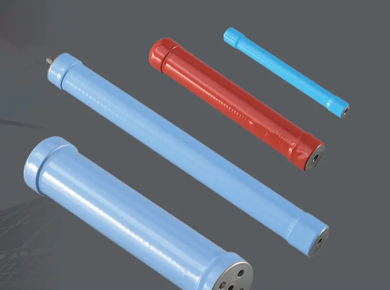
A 96 % alumina tube forms the core. Its surface is roll-coated with a resistive ink containing ruthenium oxide and glass frit. After firing at 850 °C the layer becomes an integral ceramic film only 25 µm thick. A computer-controlled laser then cuts a fine meander into the film; the longer the path, the higher the value. Because the track is planar and returns on itself, parasitic inductance stays below 400 nH—an order of magnitude lower than a spiral wire-wound part. Nickel-plated brass end-caps are pressed on and annealed, giving a robust, solderable termination that also serves as a heat spreader. Finally a high-purity silicone coating is brushed on and cured at 200 °C, providing 30 % extra creepage distance and protection against moisture and ozone.
Electrical characteristics
Resistance range: 200 Ω – 1 GΩ, tolerances down to ±0.1 %
Temperature coefficient: ±25 ppm K⁻¹ typical (25 °C – 105 °C)
Maximum continuous voltage: 3 kV – 90 kV DC depending on length
Lightning impulse: 70 kV – 120 kV (1.2/50 µs) five pulses in accordance with IEC 60115-1
Power rating: 2 W – 200 W at 25 °C, derated linearly to zero at 175 °C
Voltage coefficient: < 1 ppm V⁻¹ below 50 % rated voltage
Stability: ΔR/R ≤ 0.15 % after 1 000 h at full power and 85 °C ambient
Insulation resistance: ≥ 10 GΩ between terminations and coating (500 V test)
Thermal management
Heat flows axially to the end-caps and radially through the coating. For natural convection, a centre-case temperature of 85 °C is the usual limit; with a copper heatsink clamped to each cap this rises to 125 °C, doubling the usable power. The silicone surface allows an emissivity of 0.9, so even black anodised plates are unnecessary.
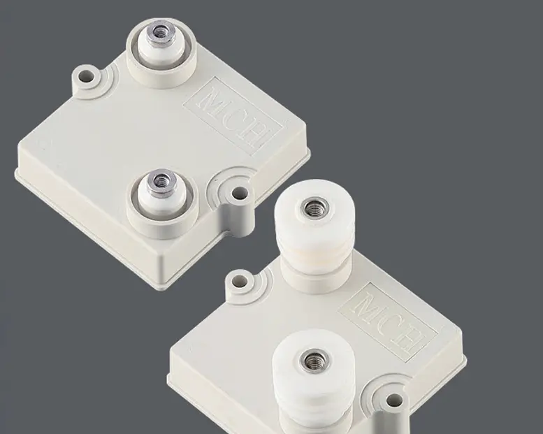
Mechanical formats
Standard devices are 30 mm – 300 mm long and 8 mm – 21 mm in diameter. Straight tinned-copper leads (Ø 0.8 mm) suit wave-soldering, while M4 or M8 stainless studs enable direct bus-bar mounting. Stud torque is 1.3 N·m maximum; over-tightening can micro-crack the ceramic. Special shapes—elliptical flats, stepped diameters, integrated spacers—are available for GIS or X-ray tube sockets where real estate is minimal.
Applications
Voltage dividers in 36 kV GIS voltage sensors
Electronic current-transformer burden and damping networks
X-ray generator tube current control
HV DC link divider boards in renewable inverters
Surge-absorption bleeder resistors in capacitor racks
Precision reference for 0.2 S metering circuits
Design checklist
Select resistance so that continuous power ≤ 25 % of rated wattage; this keeps drift below 0.1 % after 20 years.
Leave 20 % impulse margin: if the system sees 70 kV peaks, specify a 90 kV part.
Provide 1 kV mm⁻¹ external creepage; silicone coating adds 30 % safety factor.
Mount vertically when possible—convection improves by 15 % and thermal EMF errors cancel.
Always derate above 75 °C; the linear derating coefficient is 1.2 W K⁻¹ for a 100 W device.
Reliability data
Thermal shock: –55 °C ⇄ +125 °C, 100 cycles, ΔR/R ≤ 0.25 %
Moisture resistance: MIL-STD-202 method 106, 56 days, ΔR/R ≤ 0.4 %
High-frequency overload: 5 × rated power for 5 s, ΔR/R ≤ 0.2 %
Voltage overload: 1.5 × maximum continuous for 10 s, no flash-over
Summary
A thick-film high-voltage resistor delivers the unique combination of ultra-low inductance, high voltage capability and long-term stability required by modern HV instrumentation. By understanding the interplay between ink formulation, ceramic substrate and mechanical assembly, designers can specify a device that will survive decades of over-voltage, thermal cycling and moisture while maintaining the accuracy demanded by revenue-class metering and grid-protection systems.