As the demand for high-efficiency energy management and high-power-density power electronics grows in rail transit, wind power, electric vehicles, and heavy industrial machinery, traditional air-cooled braking choppers are increasingly limited by thermal performance, size constraints, and reliability. The liquid-cooled braking chopper has emerged as a leading solution in high-power applications, offering superior heat dissipation, compact design, and stable dynamic response. This paper presents a comprehensive analysis of the working principle, core components, thermal management mechanisms, technical challenges, and real-world applications of liquid-cooled braking choppers, along with insights into future development trends.
1. Introduction
The braking chopper is a critical component in variable-frequency drive (VFD) systems, designed to dissipate regenerative energy from motors during deceleration or downhill operation. When this energy is fed back into the DC bus, it can cause overvoltage issues that threaten system safety. By diverting excess energy to a braking resistor, the chopper protects the inverter and ensures stable operation.
In high-power or continuous braking scenarios, however, the thermal load becomes immense. Traditional air cooling often fails to meet the demand, leading to overheating, reduced lifespan, and system failure. The liquid-cooled braking chopper addresses these challenges with advanced thermal management, enabling reliable, compact, and efficient energy dissipation—making it ideal for next-generation industrial and transportation systems.
2. Working Principle of a Liquid-Cooled Braking Chopper
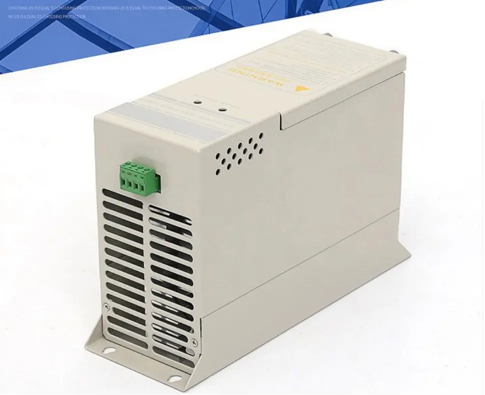
A liquid-cooled braking chopper system consists of the following key parts:
- Control unit
- IGBT power module
- Liquid-cooled braking resistor
- Liquid cold plate (for IGBT cooling)
- Closed-loop coolant circulation system
Operation Process:
- When the DC bus voltage exceeds a preset threshold due to regenerative braking, the control system activates the chopper.
- The IGBT switches on/off at high frequency, directing excess energy to the braking resistor.
- The resistor converts electrical energy into heat, which is rapidly absorbed by circulating coolant.
- The heated fluid passes through a heat exchanger (e.g., radiator or cooling tower) and returns to the system, enabling continuous thermal regulation.
This closed-loop process ensures safe voltage control and high-efficiency thermal management—critical for demanding applications.
3. Core Components and Liquid Cooling Design
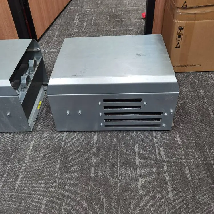
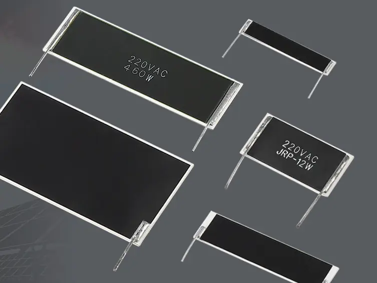
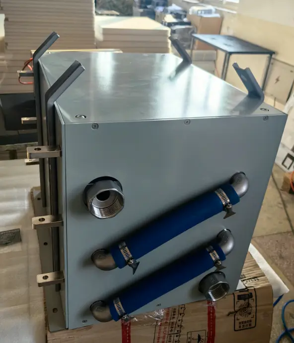
3.1 Liquid-Cooled Braking Resistor
The braking resistor is the primary heat source and the main target of liquid cooling.
- Structure: Sealed metal housing (stainless steel or aluminum) with high-temperature alloy resistors and integrated coolant channels.
- Cooling Method: Direct liquid flow over the resistor base or casing for high-efficiency heat transfer.
- Advantages:
- Power handling up to several hundred kilowatts
- 30–50% smaller footprint than air-cooled equivalents
- Low noise, suitable for enclosed or indoor installations
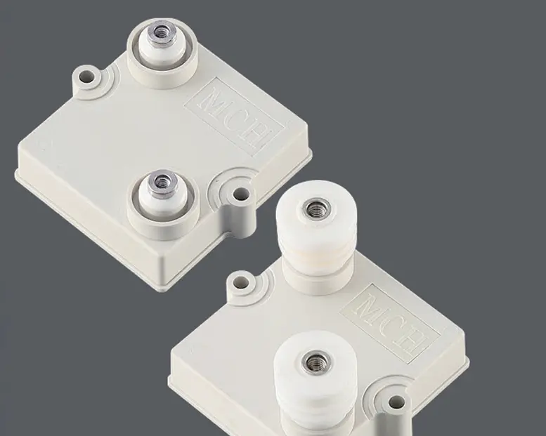
3.2 Liquid-Cooled IGBT Module
High-power IGBTs generate significant switching and conduction losses. Mounting them on a liquid cold plate enables precise temperature control.
- Coolant flows through internal copper or aluminum channels beneath the module.
- Enables higher switching frequencies (>10 kHz), improving system dynamics.
- Reduces junction temperature, enhancing reliability and extending service life.
3.3 Integrated Cooling System
A complete liquid cooling loop includes:
- Circulating pump
- Expansion tank
- Filters and sensors (temperature, pressure, flow)
- Heat exchanger (air-to-liquid or liquid-to-liquid)
This system can be integrated with the main cooling circuit of a vehicle or industrial machine, enabling unified thermal management across motors, batteries, and power electronics.
4. Key Technical Challenges and Solutions
| Poor cooling uniformity | Optimized flow channel design (e.g., serpentine or parallel paths) |
| Corrosion and scaling | Use of deionized water with anti-corrosion additives; regular maintenance |
| Leakage risk | Hermetic welding, leak detection sensors, and alarm systems |
| System complexity | Modular design with pre-installed fluid connectors for easy integration |
| High initial cost | Economies of scale and material optimization (e.g., aluminum instead of copper) |
5. Typical Applications
5.1 Urban Rail Transit
Trains experience frequent braking, generating large amounts of regenerative energy. Liquid-cooled braking choppers are used in onboard or ground-based resistor cabinets to safely dissipate energy, reduce grid impact, and support energy recovery systems.
5.2 Wind Power Generation
During grid faults or low wind conditions, excess energy must be dumped. Liquid-cooled choppers fit tightly within nacelles and offer stable performance in harsh environments.
5.3 Electric Heavy-Duty Trucks & Construction Equipment
Downhill braking produces high power loads. Integrating the liquid-cooled braking chopper into the vehicle’s thermal management system enables coordinated cooling of motor, battery, and power electronics.
5.4 Industrial Drives & Elevators
Cranes, elevators, and rolling mills require rapid energy dissipation during emergency stops or heavy-load descents. Liquid cooling ensures safety and reliability under extreme conditions.
6. Performance Comparison: Liquid-Cooled vs. Air-Cooled
| Heat Dissipation Efficiency | High (>1000 W/m²K) | Moderate (<200 W/m²K) |
| Power Density | High, compact design | Larger footprint, needs airflow space |
| Noise Level | Low (<60 dB) | High (>80 dB) |
| Environmental Suitability | Works in sealed, dusty areas | Requires clean air; prone to dust buildup |
| Maintenance | Higher initial cost, lower long-term failure rate | Lower upfront cost, fan wear issues |
| Ideal Power Range | >50 kW (high-power systems) | <100 kW (low-to-medium power) |
7. Future Development Trends
- Integration and Intelligence Move toward all-in-one modules combining power, cooling, and digital control. Support IoT connectivity, remote monitoring, and predictive maintenance.
- Advanced Materials Adoption of SiC (Silicon Carbide) IGBTs to reduce switching losses, paired with liquid cooling for higher efficiency and frequency operation.
- Waste Heat Recovery Explore using heat from the braking resistor for cabin heating or industrial preheating—improving overall energy utilization.
- Eco-Friendly Coolants Promote biodegradable, non-toxic coolants to align with sustainability and carbon neutrality goals.
8. Conclusion
The liquid-cooled braking chopper is a transformative technology in modern power electronics, solving critical thermal challenges in high-power regenerative braking systems. By efficiently removing heat from both the braking resistor and IGBT modules, it enables compact, quiet, and highly reliable operation. With growing adoption in rail, wind, EVs, and industry, this technology is poised for rapid advancement.
As material science, fluid dynamics simulation, and smart control evolve, the liquid-cooled braking chopper will become even more efficient, intelligent, and sustainable—playing a vital role in the future of green transportation and energy systems.